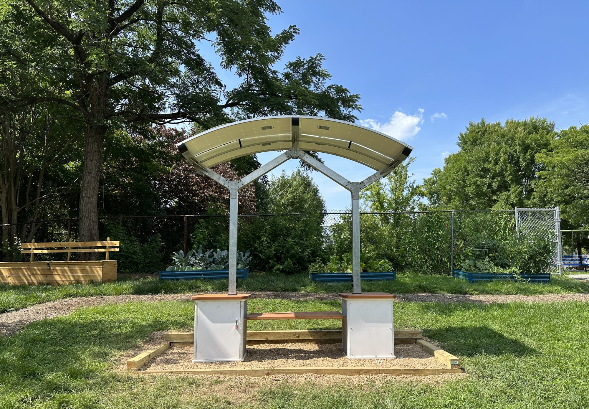
From 2022-present, Open Works has designed, prototyped, scaled, and deployed 14 Solar Stations in Baltimore City -- public benches with solar canopies that provide free wi-fi and device charging.
This project began as a collaboration between Open Works and the Central Baltimore Partnership (CBP) with, began with the goal of providing free wi-fi in neighborhoods with low rates of residential broadband. Baltimore has one of the worst digital divides in the United States, with 40% of households lacking broadband and 30% lacking a computer in the home. In 2022, CBP secured a grant from the Maryland Office of Statewide Broadband to prototype solar-powered wi-fi stations to be installed at six community and recreation centers. The 29th Street Community Center in the Harwood community of north Baltimore (above) was selected as the first site.
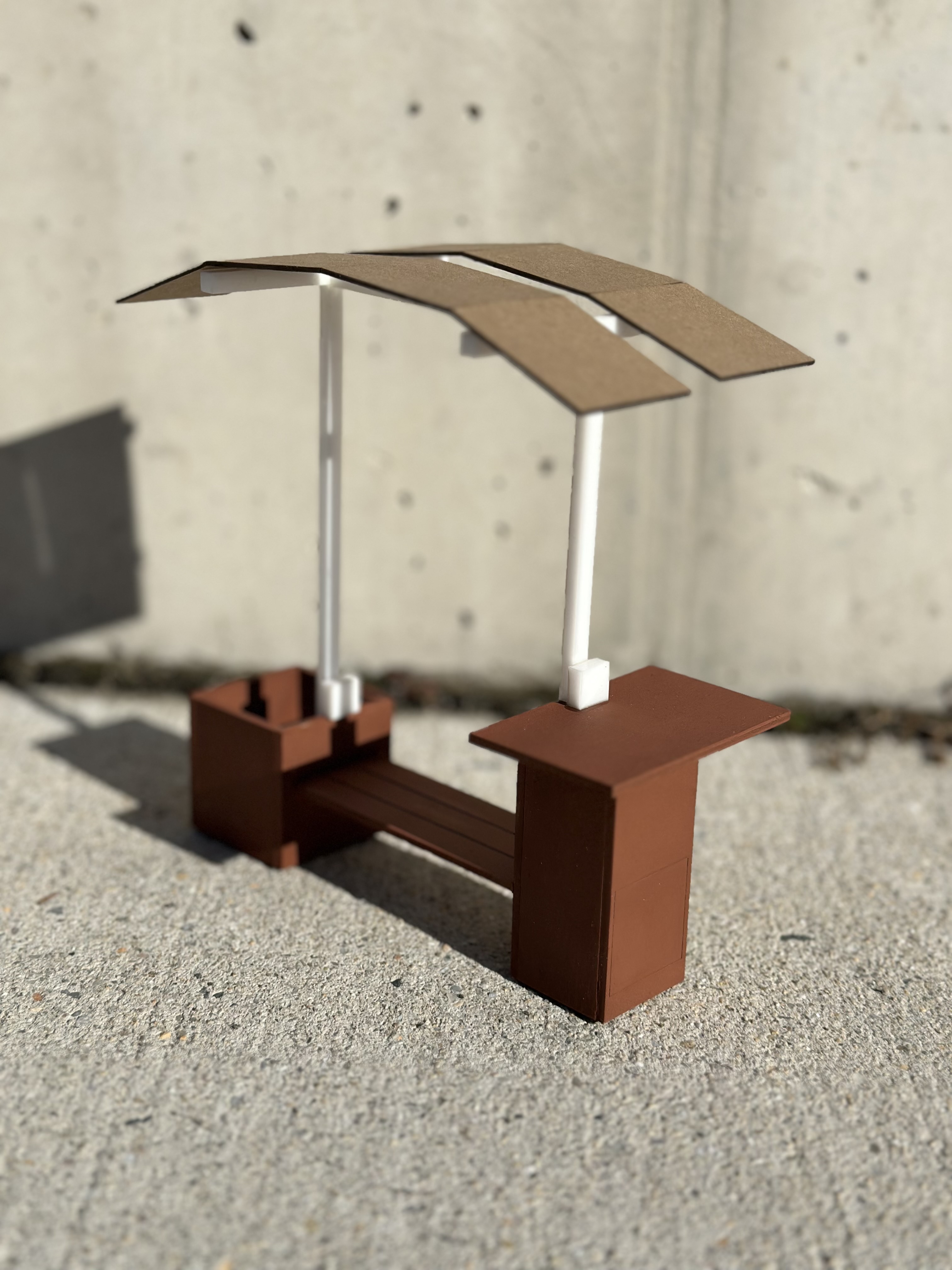
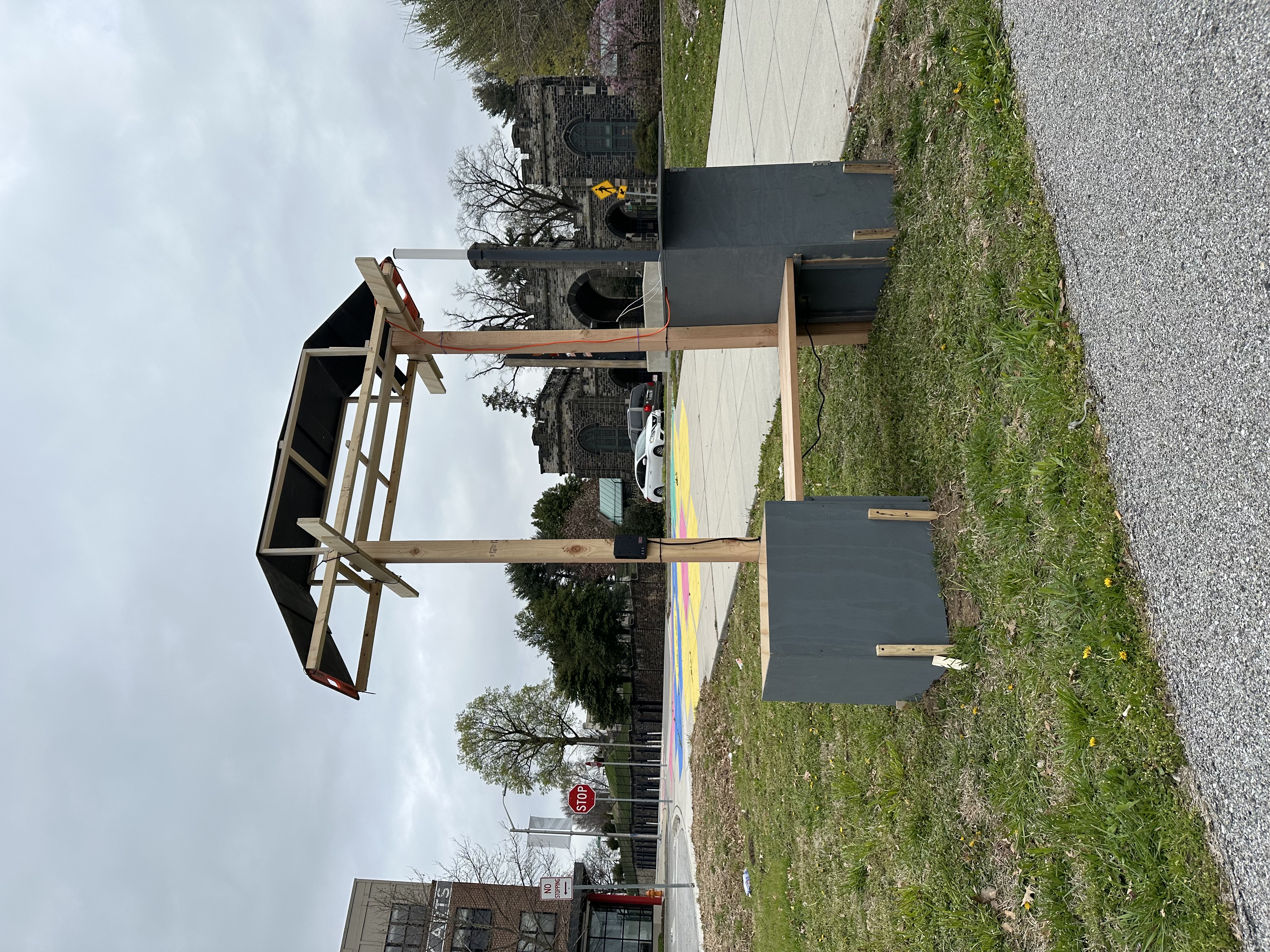
The creation of these stations involved several stages of prototyping and testing. Zach Adams and his team, including Ben, Chima, Dom, Harlock, Jamie, and Tara, worked tirelessly to bring the concept to life. The first steps included producing a 3D-printed scale model and then a full-size mock-up, which was tested at the Open Works yard from fall 2022 into spring 2023.
Feedback sessions were held with local community groups, digital equity advocates, and neighbors to ensure the design met the needs of its users. This feedback was crucial in refining the ergonomics and performance of the stations before the final models were crafted from steel and aluminum.
Open Works successfully secured additional funding through the Baltimore Civic Fund Digital Equity RFA and the AARP Community Foundation to build 8 more stations through the end of 2024.
Wi-fi is provided via 5G routers through a partnership with Project WAVES, a nonprofit ISP in Baltimore City.
In addition to these permanent stations, the team also tested and deployed mobile solar Wi-Fi stations in collaboration with the Baltimore City IT Department and the Department of Sustainability. These mobile units have been utilized at local festivals, such as Artscape in 2024, and are prepared for deployment in emergencies, providing a flexible solution to ensure digital connectivity throughout the city.
This project continues to evolve, and its impact on digital equity in Baltimore is clear as more communities gain access to essential digital resources.
This page open-sources our design for replication and improvement. We have tried to make all documentation compliant with Open Source Hardware Association (OSHWA) standards. Assembly instructions, schematics, shop drawings, and digital fabrication files are all released under a Creative Commons CC BY-SA 4.0 copyright license.
Primary design was created by Contract Services Manager Zach Adams, with engineering and fabrication support from OW staff including Ben Hobby, Nemo Harlock, Jamie Cezar, Chima Ezenwachi, Brian Menifee, Joe Bates, and Jon Bury.
¶ 1. Installed Units
¶ 2. Bill of Materials (BOM)
¶ 3. Drawings and Schematics
Solar Station drawing
Updated Main Assembly drawing
Wiring diagrams
¶ 4. Instructions
Open Works disclaims any liability arising from the use of these instructions. Electricity and lithium-ion batteries are hazardous and must be handled with care. Please use caution, wear approriate PPE, and take all other relevant safety precautions when fabricating your own station.
The solar stations contain 4 primary components:
- Solar array: 4 100-watt flexible panels mounted on a curved aluminum frame
- Power pack: inverter, battery, charge controller, and fuses contained in a waterproof suitcase
- Wi-fi: high-speed 5G router with approx. 300 foot signal radius
- Structure: foundation, bench, posts, and canopy
The solar stations are made up of subassemblies. Brief instructions for the subassemblies are provided below.
¶ Box Unit
Make 2.
- Assemble the cinder blocks and seat plates in two stages using 2 part epoxy (mix with silica thickener until mayonnaise texture). Make sure the glue ups are identical, NOT mirrored.
- Install the glued blocks into the top and bottom plates using screws in the tops and bottoms of the corner pieces.
- Paint the outward facing sides of the glued up sections using 2 part epoxy paint
- Fit the doors and back panels into the enclosure frame, but do not permanently install.
- Test fit, mark, and attach the vertical poles using bolts.
- Once the vertical poles are installed, permanently install the top and bottom plates as well as the work surfaces using four screws. Pilot drill all holes.
¶ Battery Box
- Cut plastic gussets on left side of lower section of the Apache case to make room for faceplate as shown. A dremel or wire cutters can be used. Be sure to clean up the face where the gussets were connected with a sharp chisel so the faceplate lies flush.
- Use faceplate to lay out mounting holes and IO ports.
- Cut IO holes.
- Drill out the majority of the material, starting inside the corners.
- Use a dremel or reciprocating tool to remove the rest of the material. A sharp knife or chisel can be used to clean up all the edges.
- Pilot drill holes at 2-3mm and install faceplate.
- Dry fit Deutsch Connector and inverter switch into faceplate and check the fit. Wait to install until cables have been run.
- Arrange Charge Controller, Inverter, Battery, and low voltage disconnect in the Apache case.
- Measure and cut wires.
- Pin out output wires into Deutsch connector as shown in the pinout table
¶ Arch Unit
- Deburr and Chamfer all flat pattern parts using belt sander and pneumatic chamfer tool.
- Bend all flat pattern parts to spec using hand brake. Be sure to set the pressure and radius correctly to avoid shearing the thin aluminum.
- Bend arch pieces to radius using pipe bender tool
- Weld W-frame components to y brackets using pre-cut plug holes. Don’t forget to weld in the interior stops in the “arms” of the y brackets.
- Weld Arch brackets to Crossbars.
- Weld Crossbars to W-Frame. Having a second person to assist with tack-welding is very helpful.
- Weld Arches to arch brackets and cut off excess.
- Grind and clean up welds
¶ Solar Array Assembly
Solar array: 4 100-watt flexible panels mounted on a curved aluminum frame.
- Attach long slotted ribs to center mounting plate by inserting into central cut-outs and screwing in place.
1.1 This can be done on the floor with the central plate upside down. - Mock up mounting plate, ribs, and solar panels on frame using clamps.
2.1 After all of the panels and strips have been attached to the solar array with clamps, double check the fitment. If any edges overhang, split the difference and ensure that there aren’t gaps between the plastic parts and the solar panels.
2.2 Ensure that the white border of the panels overlaps the aluminum rails with enough space to drill and screw into the metal. - Attach center mounting plate to center crossbar using self tapping screws and measure from each end to ensure it’s centered.
- Attach rib ends to end crossbars, making sure to put them under tension to match the curvature of the aluminum arches before installing
4.1 There will be several inches of overhang, which will be trimmed flush after the panels are installed - Insert solar panels into rib slots and attach to aluminum frame using self tapping screws with gasketed washers.
¶ Battery Column
- Cut wires to length.
1.1 Check length against columns and ensure excess at both ends for connectors and slack during assembly. - Strip wires at ends and prepare for pins.
2.1 Add female pins to the bottom.
2.2 Add male pins to the top. - Install bottom 8-pin Deutsch connector.
- Test connections.
4.1 Test power through cables at each pin. - Splice in connectors for Power-Out Module using Tap Splice 32" from the bottom of the cable.
5.1 Use 3-pin Deutsch connectors for AC main.
5.2 Use 2-pin waterproof connector for DC main. - Install Deutsch connector at the top of all 3 cables using the pinout from the pinout table.
- Test all connections with a multimeter:
7.1 Bottom to top.
7.2 Bottom to splice.
7.3 Top to splice. - Drop completed harness through the column.
¶ Wifi Column
- Cut wires to length.
1.1 Check length against columns and ensure excess at both ends for connectors and slack during assembly. - Strip wires at ends and prepare for pins.
2.1 Add pins to black-sheathed cable (AC wires):
2.2 Male pins at top and bottom. - Install bottom 3-pin Deutsch connector to black AC cable.
Install 2-pin waterproof connector to the bottom end of white DC cable.
4.Test connections.Test power through cables. - Splice in connectors for Power-Out Module using Tap Splice 42" from the top (W-Frame end) of the cable.
5.1 Use 3-pin Deutsch connectors for AC main.
5.2 Use 2-pin waterproof connector for DC main. - Add heat shrink and Deutsch connector to the top of all 3 cables using the pinout from the Wiring Diagram.
- Test all connections with a multimeter:
7.1 Bottom to top.
7.2 Bottom to splice.
7.3 Top to splice. - Drop completed harness through the column.
¶ Power-Out Module
Make Two
- Prep cables and connectors.
- For AC Socket:
2.1 Add 3-pin female Deutsch connector pins to black jacket 3-strand cable.
2.2 Add heat shrink.
2.3 Install Deutsch connector.
2.4 Route cables into Power-Out housing through bottom holes.
2.5 Crimp on female disconnects.
2.6 Attach to 120V AC socket through Power-Out faceplate. - For DC System (battery indicator is only included on one module):
3.1 Route cables from 2-pin waterproof connector into Power-Out housing.
3.2 Route cables from Charge Indicator and USB 12V DC socket through Power-Out faceplate.
3.3 Splice in Charge Indicator cables in parallel to USB 12V DC socket cables.
3.4 Join USB 12V DC socket cables to 2-pin waterproof connector inside housing using butt splices. - Test all wiring and connectors with a multimeter.
- Test all wiring and connectors with the battery system.
- Install into column.
- Screw all components into faceplate and housing.
- Plug in connectors to main cables.
- Mark, drill, and tap holes for M-4 screws in columns.
- Connect plugs on power module to corresponding receptacles in the column.
¶ Wiring the Arch Unit
- Connect panels in series and leave the circuit open.
- Cut wires to specified lengths:
2.1 12V passthrough: 90in (white 2-strand 14 AWG).
2.2 120V passthrough: 90in (black 3-strand 16 AWG).
2.3 12V light sensor power SEND/RETURN: 70in (2-strand 16 AWG, red/black, no jacket).
2.4 PV cable: 70in. - Lay out 2-strand white wire on the "w-frame" to mark lighting splice locations.
- Splice three 2-pin waterproof female connectors in parallel using short low-voltage wire.
- Attach male connectors to three lights and test circuit with a multimeter or power supply.
- Run 12V and 120V passthrough cables from one column bracket to the other, using stiff wire or coat hanger for assistance.
- Run the lighting circuit and PV wire through the central crossbar, leaving ends accessible from the top.
- Install light sensor and determine which wire pair will SEND/RETURN power.
- Splice SEND cable to 12V passthrough and connect to light sensor for testing.
- Connect RETURN cable to the sensor and light circuit.
- Test the circuit by blocking the light sensor and sending power; replace quick disconnects with butt splice connectors if the test passes.
- Strip wires, add pins to cables, and install DT-10 connectors according to pinout tables.
¶ Final Assembly
¶ Sub Frame (only needed for in ground installations)
- Cut wood to length.
- Assemble pedestal sections using screws. Pilot drill all holes.
- Assemble outer frame.
- Lay frame at install location and trace outline.
- Dig trench 8-10 inches deep and check that the ground is level.
- Lay pedestals out and attach to the frame.
6.1 Check that the pedestals are level.
6.2 Backfill the trench with gravel or mulch. - Ensure mounting holes are drilled in the bases of the box units.
- Attach the seat to set the width of the box unit.
- Mount the boxes to the pedestals using [hardware] screws.
¶ Installing the Complete Arch Unit
Requires:
- 3 people
- 8 pairs of collar nuts and bolts
- 2 clamps
- Masking tape
- Four 4mm Allen keys
Installation:
- Verify which end of the solar canopy has the 6-pin connector and which has the 8-pin. Rotate the assembly to match the box unit orientation.
- Use masking tape to secure the loose ends of all cable harnesses to the aluminum tubes.
- Tape the cables to the sides of the column opposite the power output modules.
- Match the taping on the arch unit to avoid extra lifting later.
- Secure a clamp to each column 2-3 inches from the top. This will support the arch unit while electrical connections are made.
- Lift the arch unit onto the columns with two people while a third person aligns the columns with the Y brackets and connects the cable harnesses.
- Once cables are connected and out of the way, remove the clamps.
7.1 Slide the arch down into its final resting position.
7.2 If the fit is too snug, gently rock the arch along its short axis to help it slide more easily. - Test fit the furniture bolts and enlarge the holes slightly with a step bit if necessary. Avoid drilling into or damaging the cables inside.
- Insert the bolts and tighten firmly.