¶ Introduction
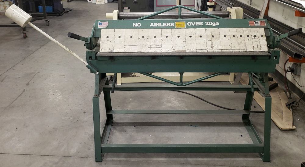
The box and pan brake is a genderal purpose tool for making bends in sheet metal. It is 48" wide and can be used to bendup to 16ga. mild steel, 20ga. stainless, and 1/8" aluminum.
¶ Shop Access
A membership or day pass is required to access the Metal Shop.
- Beware of pinch points! Keep hands and fingers away from the rolls when the machine is in operation. Keep hands and fingers clear of any gears or mechanisms. Make sure guard is in place before operating machine.
- Keep clear of moving objects! Always be aware of the position of the clamp handle and the counterweight. They are heavy and can swing back suddenly causing serious body or head injuries.
The box and pan brake is not currently covered within a Shop Safety class at Open Works. Members and day pass users must check in with a Community Technician to be trained on the box and pan brake.
¶ Machine Reservations
The box and pan brake does not require a machine reservation and is available on a first-come first-serve basis.
¶ Machine Overview
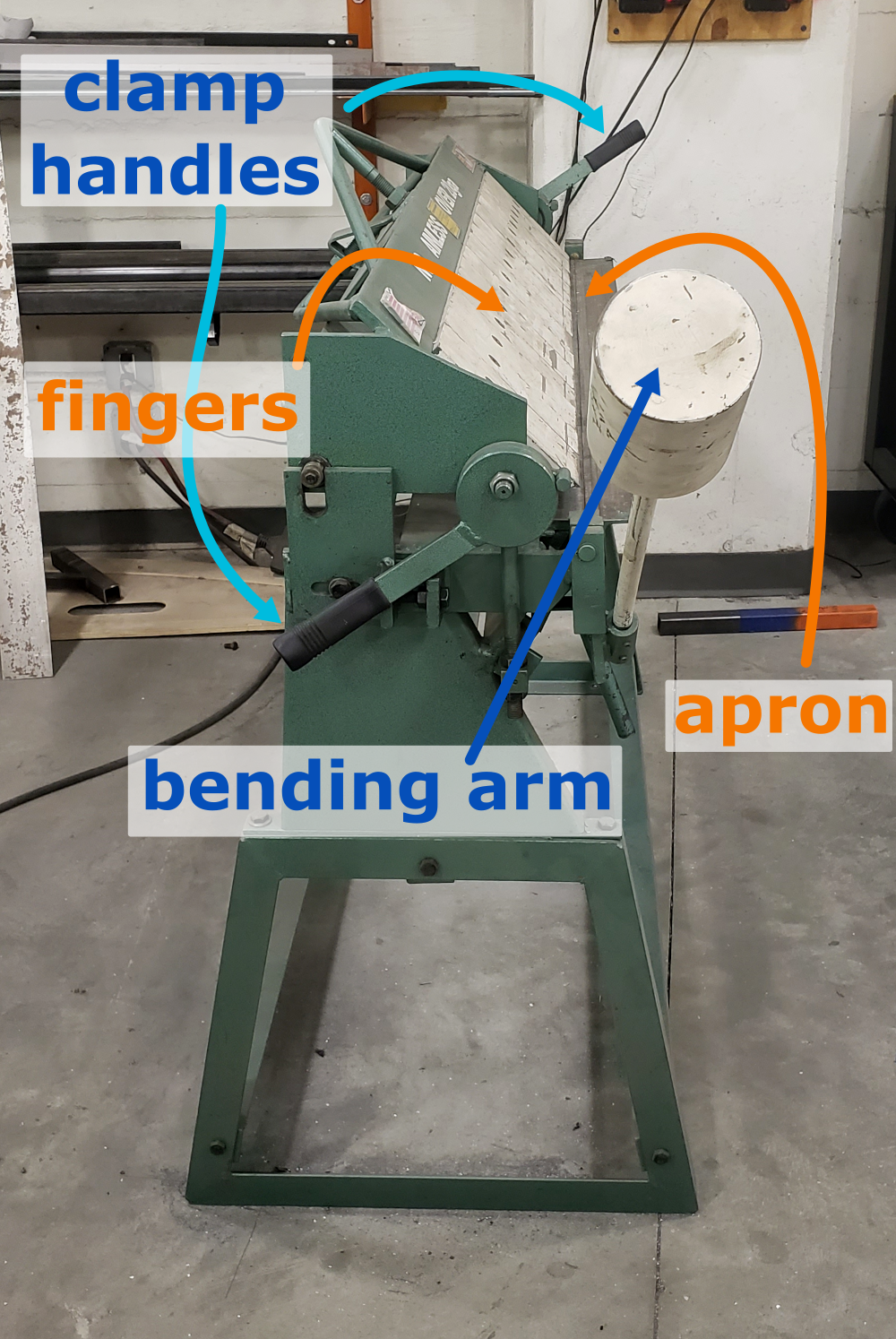
- The brake has a set of fingers, which clamp down on your workpiece. They are removed or rearranged for specific bending operations, and set in the upper portion of the machine. The fingers are removed with a hex key and remounted so the fingers are parallel to the rail.
- Clamping handles on either side of the brake lift the upper portion in order to set your work under the fingers. To lock, lift the handles until they fully lock and point to the rear of the brake. It's necessary to fully lift both levers to adjust the fingers. Don't force the clamps to lock down on your metal.
- The bending leaf is the hinging table that the workpiece rests on. Once the fingers are clamped down on the piece, lift the bending leaf handle upwards, slowly. The bending leaf will push your material up towards the fingers.
- When the piece can't be bent anymore, you have probably hit the angle adjustment stop. This is a collar on a rod that connects to the bending leaf and can be adjusted at different points along the rod to control the degrees of the bend.
Short workpieces should be bent in the center of the brake. This equalizes strain on the machine. Never force the clamps down.
¶ Machines Available
- One TK 1648 Box and Pan Brake.
¶ Parts of the Machine
Click to see a labled diagram of the machine!
¶ Material Considerations
¶ Acceptable Materials:
16ga. and under Mild steel
¶ Forbidden Materials:
over 20ga. stainless steel
¶ Safety
Personal Protective Equipment (PPE):
Sturdy, close-toed shoes must be worn at all times.
- If another member or day pass user is operating power tools within the Metal Shop then everyone in the shop should wear hearing protection.
¶ Step-by-Step Guides
¶ Before You Begin
-
Mark your material and know the angle of the bend you want.
-
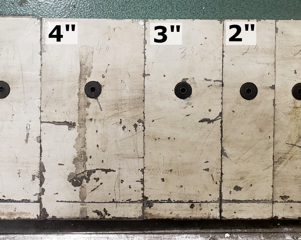
Setting the fingers
The fingers can be removed and repositioned on the holddown assembly by moving the clamp handles fully to the rear and loosening the finger clamp screws. Reposition the fingers to assemble the desired width and secure the fingers to the holddown by tightening the finger clamp screws. Be certain that the tops of the fingers are flush and parallel with the milled edge on the holddown and that the finger clamps are parallel with the bottom edge of the holddown. As a general rule, use the wider fingers first and fill in with the narrower fingers. Small gaps between the fingers may be left with no adverse effect to the work piece. The maximum depth of the box or pan, which can be bent, is four inches.
-
Set maximum angle or Set stop for repeat bends
Adjust the collar on the guide rod on the back right of the machine to set the maximum angle. The stop collar is secured in place with a setscrew.
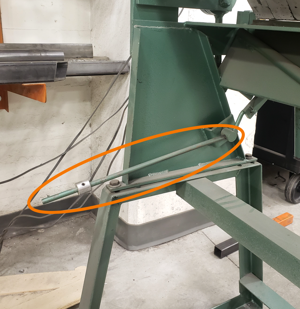
The maximum degree of bend is approximately 140 degrees. Due to the ”spring back” in various materials some overbending may be required to get the desired bend angle.
- Allowing for metal thickness
The holddown assembly must be adjusted to allow for clearance when making bends according to the thickness of the material being formed. This adjustment is made by slightly releasing the clamping pressure on the clamp handles and moving the forward edge of the fingers back, away from the edge of the clamp block on the base. This movement is accomplished by loosening the bracket lock bolts – one on each end of the base assembly – and turning the adjusting bracket nuts to move the edge of the fingers toward or away from the edge of the clamp block.
- Clamping pressure
Clamping pressure should be adjusted according the thickness of the material being worked. A common cause of bending and forming problems is excessive clamping pressure. Clamping pressure should be adequate to hold the material securely in place but not so great as to require undue effort in locking the clamp handles. Clamping pressure is adjusted by turning the nuts on the threaded rod portion of the yoke assembly below the clamp swivel. The lift of the holddown assembly is adjusted by turning the nut above the clamp swivel. When the clamping pressure is properly adjusted, lock the nuts against the clamp swivel to prevent any change in adjustment.
¶ Using the Machine
- Bending is accomplished by clamping the work piece under the holddown assembly so that the desired line of bend is held at the forward edge of the fingers
- Pushing the clamp handles toward the rear of the brake opens the holddown of the brake. Insert the material to be bent into the opening between the holddown and base assembly and clamp the material in place by pulling the clamp handles forward.
- Pushing/pulling on the bending arm to move the apron assembly until the desired degree of bend is obtained.
¶ Machine Maintenance
¶ Motion is 'sticky' or requires force even when the machine is unloaded
Straighten the angle stop out
¶ Counterweight alignment
The counterweight on this brake can be adjusted to balance the apron for ease of operation. Loosen the setscrews and raise or lower the counterweight to achieve the desired degree of balance. Be certain to retighten the setscrews thus securing the counterweight in place.
¶ Overbending
The holddown assembly should be moved back on the end where the overbending occurs by slightly unclamping the clamp handle, loosening the bracket lock screw and turning the adjusting bracket screw. When the correction is made retighten the bracket lock screw. When your brake was assembled at the factory it was adjusted for proper operation. Due to handling and repositioning, the brake may require adjustment and alignment. Read the adjustment and operating instructions completely before making any adjustments. Operate the brake and bend some material first before attempting any major adjustments.
¶ Base alignment
The clamp block on the base of the brake should be straight. This is the reference point for all of the other alignment operations in adjusting the brake. Raise or lower the center of the brake by adjusting the center truss rods.
NOTE: Your brake has four truss rods, which facilitate adjustment of the brake’s three primary weldments. The holddown has two truss rods bracing the top and rear of the weldment. Adjustments are accomplished through rotation of the nut located on the studs mounted perpendicular to the weldments.
¶ Holddown Alignment
The forward edge of the fingers on the holddown assembly should be even and parallel to the edge of the clamp block on the base. Release any clamping pressure on the holddown assembly by pushing the clamp handles slightly to the rear. Loosen the bracket lock screws at each end of the holddown assembly and turn the adjustment bracket nuts to move the forward edge of the fingers to the forward edge of the clamp block. Check to see that the forward edge of the fingers are flush with the edge of the clamp block on the base along the entire length of the brake. The central portion of the holddown assembly can be adjusted forward/backward and up or down via truss rod adjustment.
¶ Troubleshooting
¶ References
Instructions adapted from TK 1648 Box & Pan Brake manual.